Retrieve the Sunlight Cluster and Management network information - Receive UI access
This section describes the process for obtaining useful information about the Sunlight cluster and management network in a user-friendly way.
More specifically, the network information that can be obtained refers to the IP address ( allocated to the Sunlight controller statically or from an external DHCP server) and the default Gateway of the controller network. Moreover, the user is able to retrieve the VLAN ID (in case the default VLAN option is enabled according to step 4 of the installation process Install on premise), as well as the Chassis and Blade IDs of each node (configured in step 5) and the NV channel ID (configured in step 7), which offers clusters isolation in the same subnet.
The Sunlight platform provides the aforementioned network management details to the end users each time the system is booted up, by displaying this information as an output either via the Serial over Lan (SOL) interface or via the VGA/iKVM console.
This solution requires an IPMI-LAN interface implemented for each node. Please visit the following link for additional information on how to configure and setup an IPMI static interface on a Sunlight appliance. How to setup static IPMI-LAN on a Sunlight appliance
Following the system boot, the user is able to choose one of the options below:
- Retrieve the cluster and management network information via IPMI SOL (Serial Over Lan)
- Retrieve the cluster and management network information via VGA/iKVM console
Retrieve the Cluster and Management network information via IPMI SOL
For this option, the Serial Over Lan (SOL) configuration is required to be enabled in the BIOS settings of each node. Please check the Sunlight appliance BIOS settings, as described in the following link, in order to ensure that the SOL option is enabled: Enable BIOS SOL
Warning
Please check the "Onboard Video OPROM" bios setting is on LEGACY mode.
Once the IPMI interface has been properly configured and the SOL option is enabled, a Serial Over Lan (SOL) connection can be launched remotely on that IPMI interface, using the ipmitool (for Linux), as explained in detail below, or by browsing the assigned IPMI address.
How to use the IPMI tool commands (for Linux)
-
First, update Linux’s package repository, by running:
sudo apt update -
Install IPMItool on Ubuntu, by using the following command:
sudo apt install ipmitool
Useful ipmitool commands :
-
Power start/stop/reset/status management actions on the Sunlight appliance
ipmitool -I lanplus -U
-P -H power start/stop/reset/status -
Launch IPMI SOL console
ipmitool -I lanplus -U <username> -P <password> -H <Host IPMI address> -e '#' sol activate
Launch SOL to display the information of each node
Follow the next steps for acquiring cluster and management network information of the controller master node:
-
Activate the IPMI and acquire the SOL console of the controller node (from a Linux terminal)
ipmitool -I lanplus -U <username> -P <password> -H <Host IPMI address> -e '#' sol activateController node IPMI configuration example :
IPMI address : 192.168.2.116
                        username/password : ADMIN/ADMIN
ipmitool -I lanplus -U ADMIN -P ADMIN -H 192.168.2.126 -e '#' sol activate
-
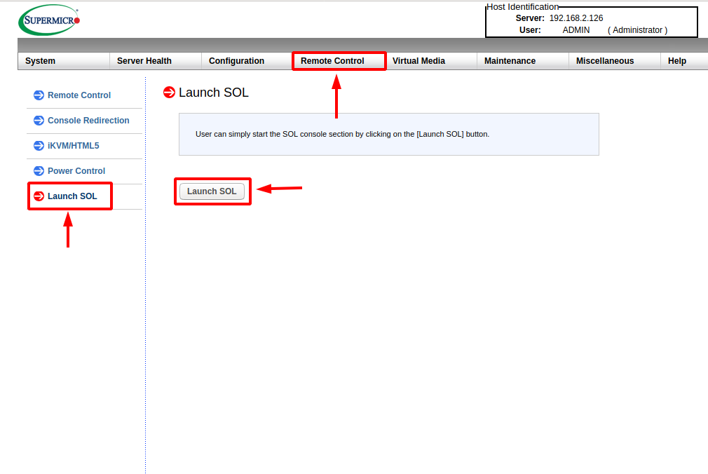
As an alternative option, you can just browse the assigned IPMI address of the desired node, enter the username/password credentials and launch the SOL console from the power control tab, as illustrated below.
-
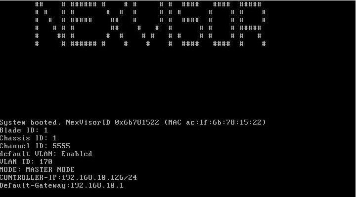
Once the master node is booted/rebooted (either manually or via ipmi), the corresponding output is provided on your SOL session:
 #####  #     # #     # #       ###  #####  #     # #######
#     # #     # ##    # #        #  #     # #     #    #
#       #     # # #   # #        #  #       #     #    #
 #####  #     # #  #  # #        #  #  #### #######    #
      # #     # #   # # #        #  #     # #     #    #
#     # #     # #    ## #        #  #     # #     #    #
####### ####### #     # ######  ### ######  #     #    #

#     #               #     #
##    # ###### #    # #     # #  ####   ####  #####
# #   # #       #  #  #     # # #      #    # #    #
#  #  # #####    ##   #     # #  ####  #    # #    #
#   # # #        ##    #   #  #      # #    # #####
#    ## #       #  #    # #   # #    # #    # #   #
#     # ###### #    #    #    #  ####   ####  #    #

System booted. NexVisorID 0x6b781522 (MAC ac:1f:6b:78:15:22)
Blade ID: 1
Chassis ID: 1
Channel ID: 5555
default VLAN: Enabled
VLAN ID: 170
MODE: MASTER NODE
CONTROLLER-IP:192.168.10.126/24
Default-Gateway:192.168.10.1
As you can notice from the serial output above, the controller IP address, the default Gateway of the Sunlight controller network, the default VLAN ID (in case this VLAN option is enabled) as well as the Nexvisor Channel ,Chassis and Blade IDs values of this node are displayed.
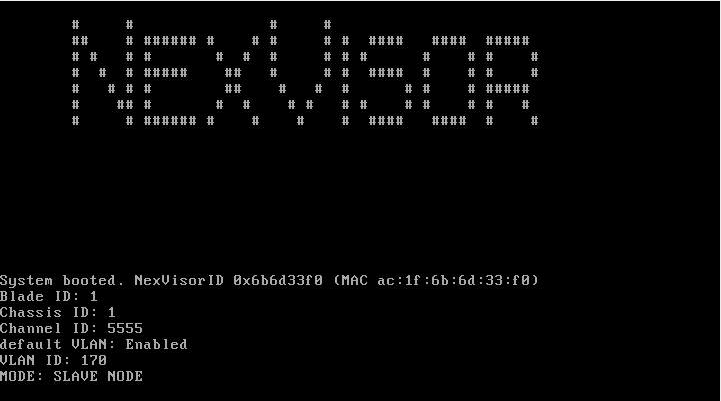
Correspondingly, once the slave node is booted/rebooted, the Serial Over Lan (SOL) output is displayed, as it is illustrated in the example below:
     #####  #     # #     # #       ###  #####  #     # #######
    #     # #     # ##    # #        #  #     # #     #    #
    #       #     # # #   # #        #  #       #     #    #
     #####  #     # #  #  # #        #  #  #### #######    #
          # #     # #   # # #        #  #     # #     #    #
    #     # #     # #    ## #        #  #     # #     #    #
     #####   #####  #     # ####### ###  #####  #     #    #

    #     #               #     #
    ##    # ###### #    # #     # #  ####   ####  #####
    # #   # #       #  #  #     # # #      #    # #    #
    #  #  # #####    ##   #     # #  ####  #    # #    #
    #   # # #        ##    #   #  #      # #    # #####
    #    ## #       #  #    # #   # #    # #    # #   #
    #     # ###### #    #    #    #  ####   ####  #    #


System booted. NexVisorID 0x6b6d33f0 (MAC ac:1f:6b:6d:33:f0)
Blade ID: 1
Chassis ID: 1
Channel ID: 5555
default VLAN: Enabled
VLAN ID: 170
MODE: SLAVE NODE
Retrieve the Cluster and Management network information via the VGA/iKVM console
-
Connect the VGA port of each cluster node to the corresponding VGA port of a monitor
-
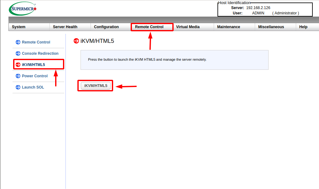
lternatively, just browse the assigned IPMI address of the desired node, enter the username/password credentials and launch the iKVM console from the power control tab, as illustrated below.
-
Once the master node is booted/rebooted (either manually or via ipmi), the following output is displayed on your monitor/iKVM console:
As you can notice from the VGA output of the controller node above, the IP address, the default Gateway of the Sunlight controller network, the default VLAN ID (in case this VLAN option is enabled) as well as the Nexvisor Channel ,Chassis and Blade IDs values of this node are displayed.
Correspondingly, once the slave node is booted/rebooted the VGA/iKVM output is displayed, as illustrated in the example below:
Master Failover Use Case
It is important to note that the user is able to retrieve the cluster management network information, even if a master failover occurs in the system. This requires for the cluster to be properly configured, as described in the section "Enable Master Fault Tolerance" of the following user guide: Automatic Master Failover.
The user is able to choose one of the two options, as described above, in order to retrieve the network information of the cluster, either via IPMI SOL or VGA/iKVM console output. It should be noted that the IPMI module and the SOL BIOS settings (in case the SOL option is selected) of the failover master (fomaster) node should be properly configured in advance.
For the fomaster node, follow the steps 1-2 for each option accordingly, as described in the previous section. If the master node becomes unresponsive and the controller on the failover master node is properly booted up, the following information will be displayed based on the selected option:
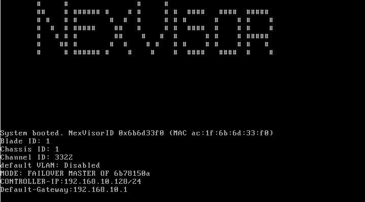
The following output will be displayed on the fomaster session in case the IPMI SOL option selected :
     #####  #     # #     # #       ###  #####  #     # #######
    #     # #     # ##    # #        #  #     # #     #    #
    #       #     # # #   # #        #  #       #     #    #
     #####  #     # #  #  # #        #  #  #### #######    #
          # #     # #   # # #        #  #     # #     #    #
    #     # #     # #    ## #        #  #     # #     #    #
     #####   #####  #     # ####### ###  #####  #     #    #

    #     #               #     #
    ##    # ###### #    # #     # #  ####   ####  #####
    # #   # #       #  #  #     # # #      #    # #    #
    #  #  # #####    ##   #     # #  ####  #    # #    #
    #   # # #        ##    #   #  #      # #    # #####
    #    ## #       #  #    # #   # #    # #    # #   #
    #     # ###### #    #    #    #  ####   ####  #    #

    System booted. NexVisorID 0x6b6d33f0 (MAC ac:1f:6b:6d:33:f0)
    Blade ID: 1
    Chassis ID: 1
    Channel ID: 3322
    default VLAN: Disabled
    MODE: FAILOVER MASTER OF 6b78150a
    CONTROLLER-IP:192.168.10.128/24
The following output will be displayed on the fomaster session in case the VGA/iKVM console option is selected :
As you can notice in both options, the controller IP address, the default Gateway of the Sunlight controller network, the default VLAN ID (in our case now the VLAN option is disabled) as well as the Nexvisor Channel ,Chassis and Blade IDs values of this node are displayed.