Configure Network Settings
The next step is to configure the network resources of the system. When deploying a server workload, it is possible to configure either public networks, any number of virtual custom networks, or dedicated networks and map those networks to physical interfaces.
-
Public Nerwork : Each public network is attached to a physical network A -NIC 0 and a physical network B -NIC 1 that correspond to the 10GBit physical ethernet ports on the blade.
-
Dedicated Network : this network uses one of the two available network ethernet interfaces(NIC0/1) as a dedicated port. For further info please visit : Dedicated Networks.
-
Virtual Network : The virtual SDN overlay network implementation is extremely efficient, providing native bandwidth scaling per physical ethernet path, without any software overlay overhead (which are commonly introduced with implementations of SDN protocols such as VxLAN or GRE). The virtual SDN overlay option can scale up to an unlimited number of virtual networks and does not rely on any network assisted VLAN protocols. It allows you to aggregate the physical network paths (A and B) in order to scale up throughput, whilst providing Ethernet level secure isolation.
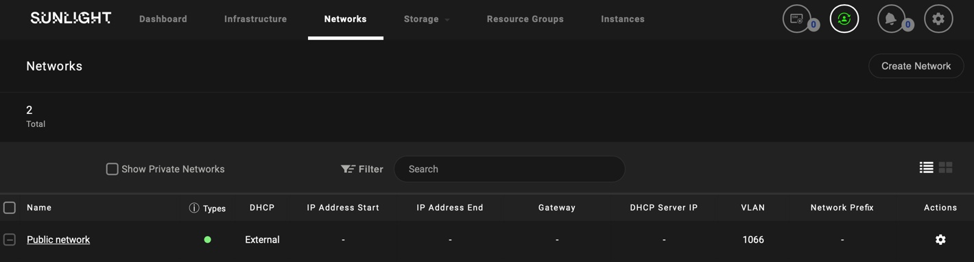
Public Networks
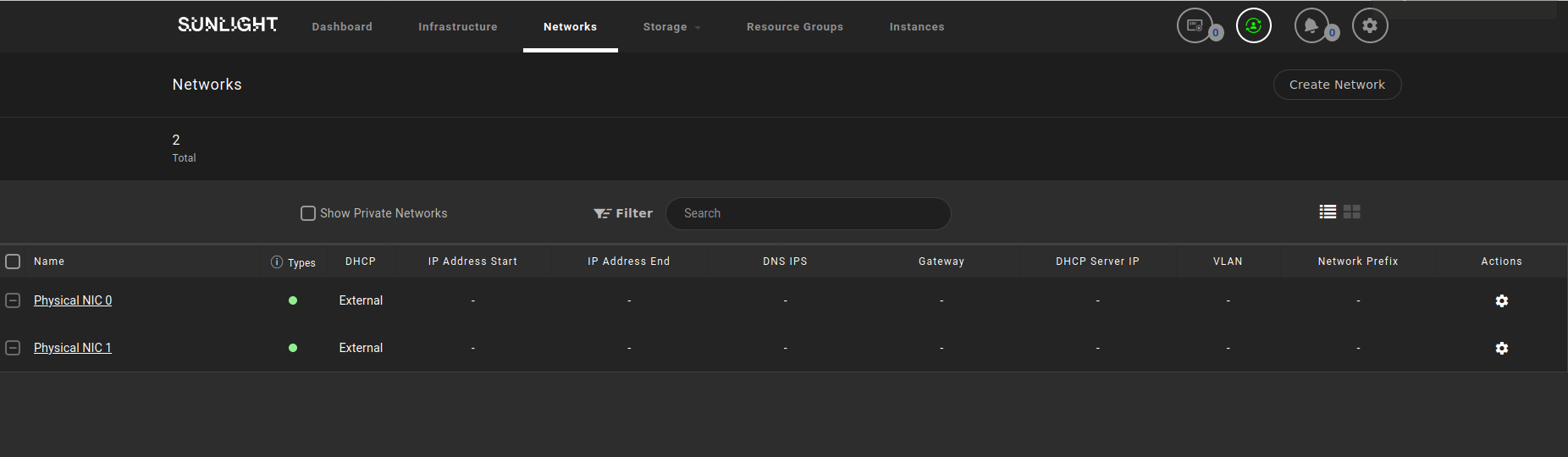
The system comes pre-configured with Public Networks NIC0 and NIC1 at initialization time.
The IP address assignment behaviour of a public network can be configured with the following DHCP options :
-
External - directly attached to physical interfaces and IP addresses assigned from external DHCP server (default).
-
Static - configured with static IP address assignment, attached directly to physical interface.
Virtual Networks
The virtual SDN overlay option is the recommended approach for any communication between workloads, running across the system, which does not necessarily require external routable traffic access.
To set up a virtual network, please follow the next steps:
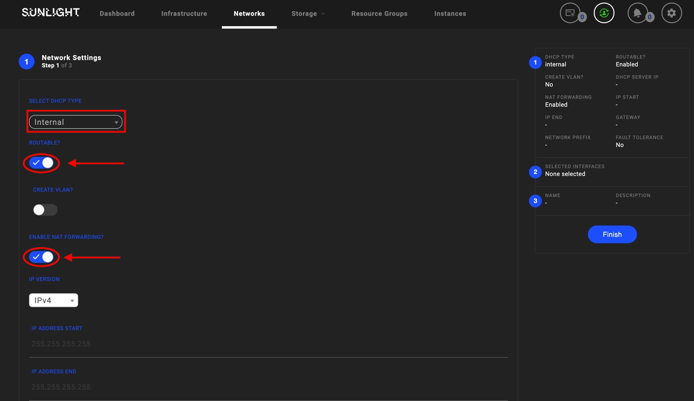
Step 1 - Choose the IP address assignment method:
The first step is to configure the IP address assignment behaviour for this network. The administrator can choose one of the following virtual network options, referring to the DHCP type:
-
External - directly attached to physical interfaces and IP addresses assigned from external DHCP server.
-
Internal - virtual private network assigned with internal DHCP IP addresses.
-
Static - configured with static IP address assignment, either attached directly to physical interfaces or isolated internally for virtual private networks.
Note
-DHCP assignment of addresses are based on server workload network interface MAC address -Static IP assignment configured into the server workload is using the cloud-init logic
Network settings offer two additional options:
- Routable and NAT Forwarding: Should be enabled in cases where Internal networks are available, in order to establish internet access, as shown in the following image.
Warning
Be aware that in the case of Internal Routable Network, the DHCP server IP address should be different from the Gateway IP address, in order not prevent DHCP serving IPs to the outside world.
Warning
Be aware that in case of Internal DHCP routable network, the IP address x.x.x.254 is reserved by the system. This IP address cannot be allocated by the user in the provided 'IP Address End' range of the custom network.
- IPv4 -IPv6 supported versions
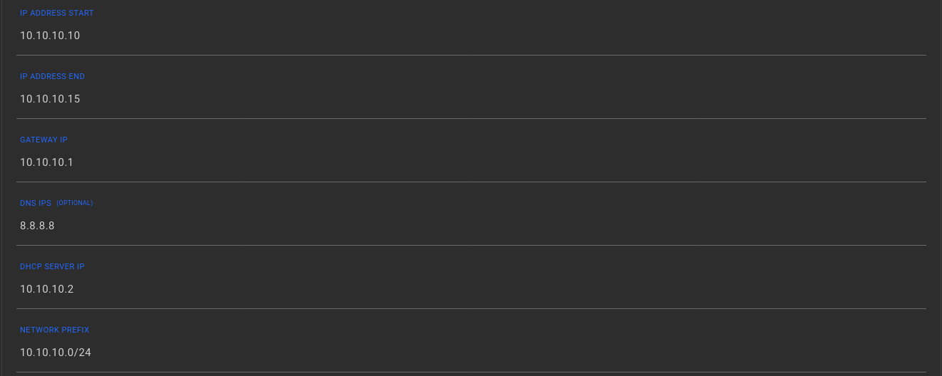
Please ensure that all the corresponding network fields, such as IP Address Start , IP Address End , Gateway IP, DNS IP(s) , DHCP server IP and Network Prefix are properly configured, in order to avoid complicated network diagnostic issues, when communication between server workloads is performed.
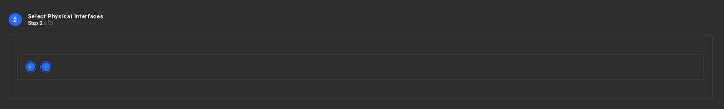
Step 2 - Select the physical paths to carry traffic:
Select the physical paths for the virtual network, which should be used in order to send and receive traffic. You can physically separate traffic between virtual networks if performance isolation is required. The physical paths selected will be used to transmit aggregated packets to other virtual network members.
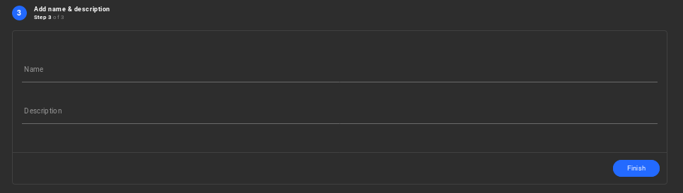
Step 3 - Finalise the network creation wizard:
Enter the Name and Description for your new virtual network. Select the Finish button to instantiate the network.
Public Network Redundancy
- Step 1 : Configure Switch with VLAN assignement VLAN Switch Configuration.
- Step 2 : Configure the default VLAN, as described in Step 5 of the Installation process : Configure VLAN.
Now the system comes pre-configured with a Public Network, which is attached directly to a redundant physical interface at initialization time, as illustrated below.
The IP address assignment behaviour (DHCP/Static) of this redundant public network can be configured in the same way as described above.