VLAN Network Redundancy
Reliable networks are more important than ever, as companies use them to access the cloud resources. For many enterprises, their networks are the primary point of contact for delivering products and services to their customers. For this reason a redundancy or disaster recovery plan should identify the critical components of the network, where a failure would cause significant outages. Consequently, in an event of failure with various communications links, redundancy allows the network to remain in service by providing alternative communications paths.
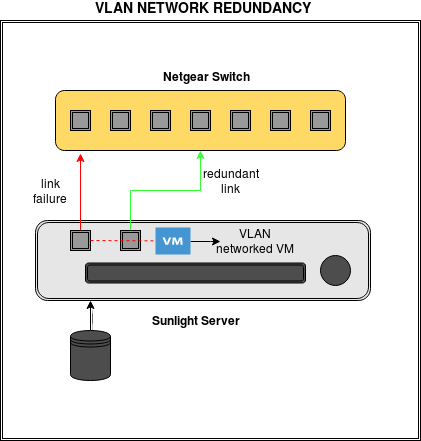
Sunlight introduces redundancy into VLAN networks, in order to improve reliability. In case one of the available physical network interfaces (NIC - attached to a VLAN virtual network) fails, an alternative one will be automatically available to take over the network connectivity, between the physical nodes.
Note
VLAN Network fault tolerance feature does not apply for the physical interface NIC 0, which is attached to master node.
Setting up a redundant VLAN Network
At a higher level, network administrators can set up a new reliable redundant VLAN network, through the Network Configuration section, by following the steps reported below:
-
Click on "create network".
-
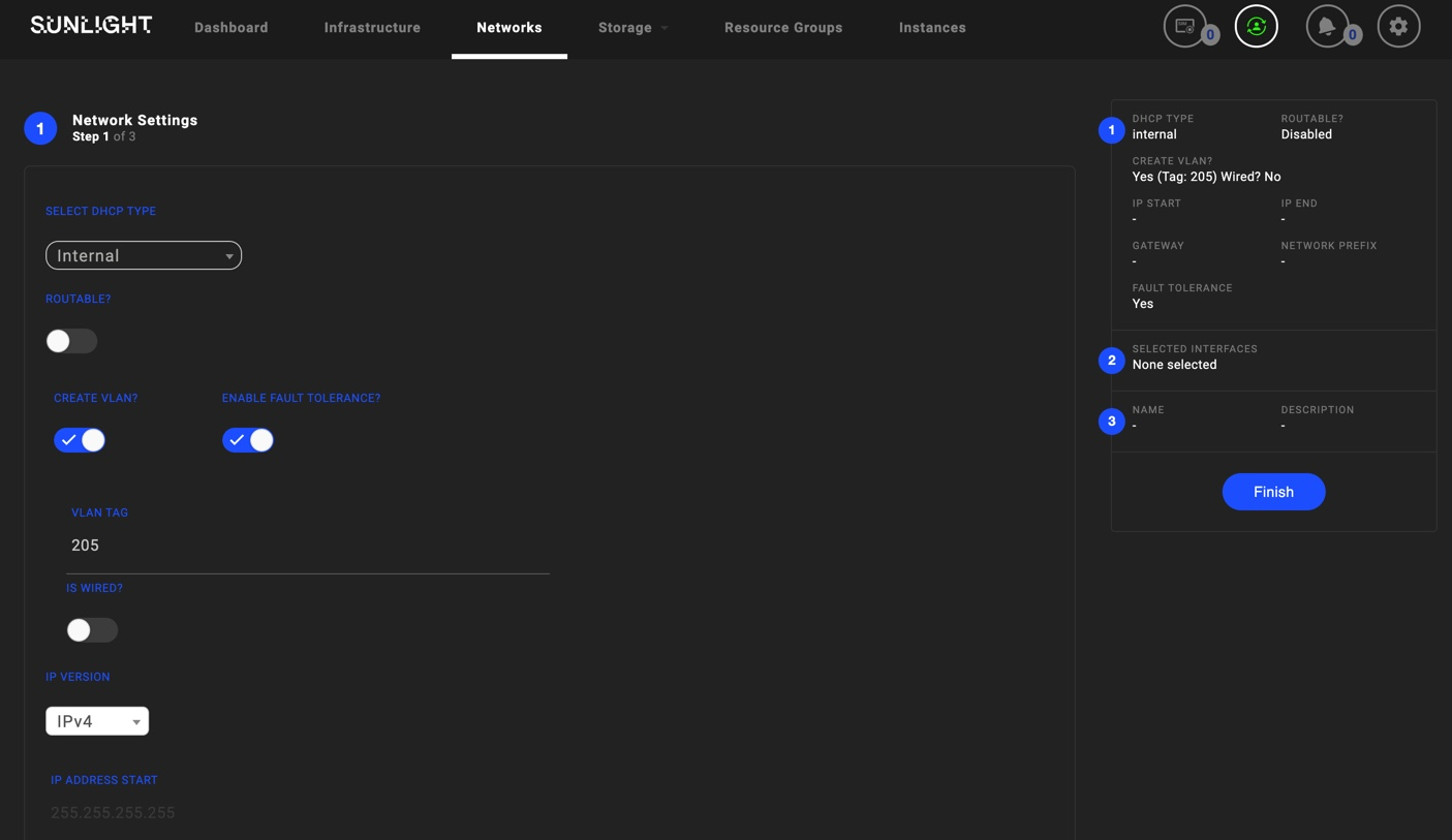
Choose the DHCP type of this network. The options (External/Internal DHCP type) use external and internal Gateway respectively.
Warning
In the case of "Static" DHCP type, the user should also enable the "IS EXTERNAL GATEWAY", in order to allow the traffic passing through other private networks or through the external world (Internet) as shown in the figure below.
-
Enable "CREATE VLAN" and "ENABLE FAULT TOLERANCE" options.
-
Type a desired VLAN Tag.
Netids for VLAN networks have BIT [63] configured. BITs [11:0] of VLAN netids hold the VLAN Tag.VLAN Tag 0 is reserved.
Warning
Valid VLAN Tags range from 1 to 4095.
-
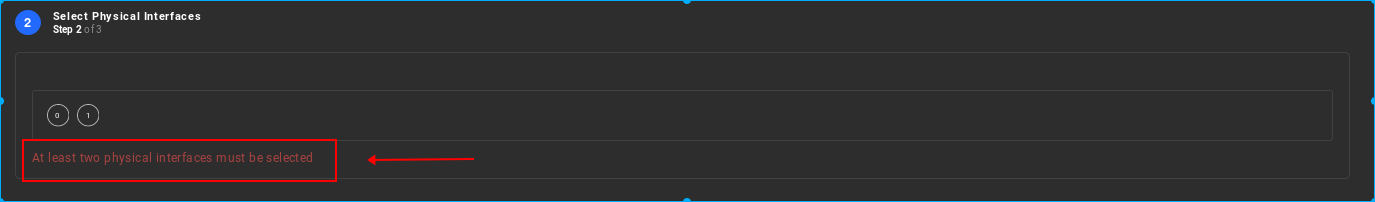
Select one prime active as well as the passive redundant physical interfaces of the two available (NIC0 or NIC1), on which this VLAN configured virtual network interface will be attached.
Initially, both NICS are deselected, as shown in the image below.
Warning
It is obligatory to select two network interfaces (one active and one passive)
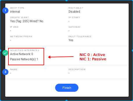
As depicted in the following image, NIC 0 has been selected as the prime active attached network interface to VLAN virtual network, while NIC 1 has been selected as the passive redundant interface. In case of failure on the active physical interface NIC 0, the passive interface NIC 1 will take over the network connectivity automatically.
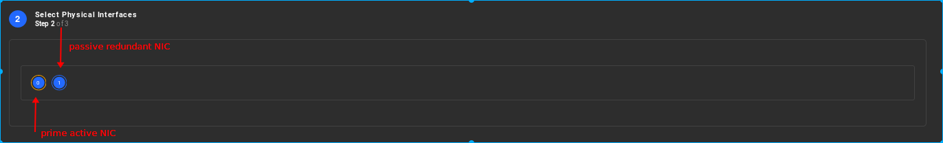
You are able to check the information box at the top left corner of the page, before proceeding to the finalization step, in order to verify the network interfaces' roles, as illustrated in the following image:
The next steps for configuring this virtual network are exactly the same as the ones described in the network configuration section.