Getting Started
The Sunlight support team is on standby to assist with any installation and configuration issues you may encounter. Link : support portal
Note
In case your system is shipped with a preinstalled Sunlight Enterprise Software platform, you can skip this step and navigate straight to System Configuration.
Note
To gain access to the installer images, please submit a request via our online support portal support portal and a Sunlight representative will get in touch to provide instructions.
In order to initialize the Sunlight Enterprise Software platform installation, please ensure that a minimum of 1 x 32GB USB thumb drive is available, such as the 32GB SanDisk Ultra Fit USB 3.0 flash drive.
Once the USB image is downloaded, please transfer the data to the raw USB flash drive (the image contains its own partition structure so the downloaded image should be transferred directly to the root directory, not an existing partition). The method for writing the image on the USB flash drive may vary, depending on the type of the Operating system you are using.
For additional information on installing the provided images, please visit the following links: - For MAC systems - For Windows systems
At this stage it must be decided which physical blade you wish to designate as the master node to host the cluster controller. In practice, any blade can be used as a master node. Please proceed to powering on the 4 nodes for which the USB boot image has been downloaded for.
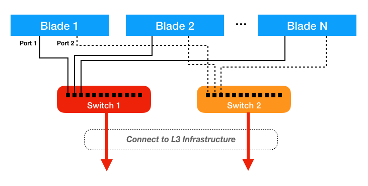
All of the 10GBit LOM NICs on the blades have to be cabled together into a single logical Layer 2 ethernet network segment. For redundancy reasons and in order to ensure the optimal performance of the High Availability algorithms, we strongly recommend using separate switches as indicated in the diagram below:
Please read the tutorials of BIOS settings for different hardware platforms, in order to make sure that the installation procedure meets the minimum requirements for running the Sunlight Enterprise Software.
Note
A keyboard must be attached for navigating through the configuration utility (for a remote access, the IPMI interface should be used). Use the TAB key to scroll through the menu or input fields.
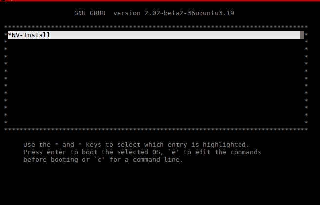
Insert the USB drive and boot up the system. The installation process is performed through the following steps:
Press 'crtl+x' to initiate the Installation process
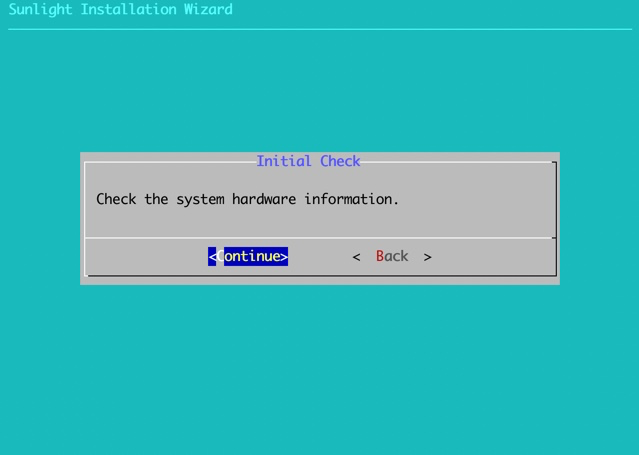
The first step is to inspect the system hardware information, in order to ensure that the system meets the requirements for the Sunlight Enterprise Software platform installation.
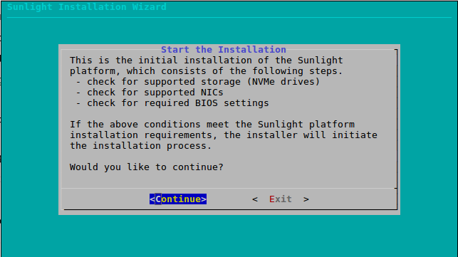
Select continue to proceed to the detection of hardware requirements:
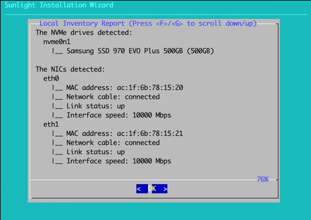
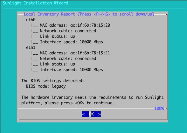
The results are displayed along with a message of whether the system meets the specified requirements. Press ok to proceed:
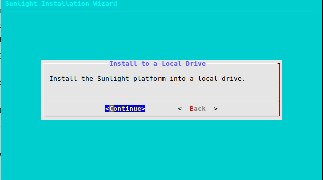
In the next step, select "continue" to install the Sunlight platform into a local drive:
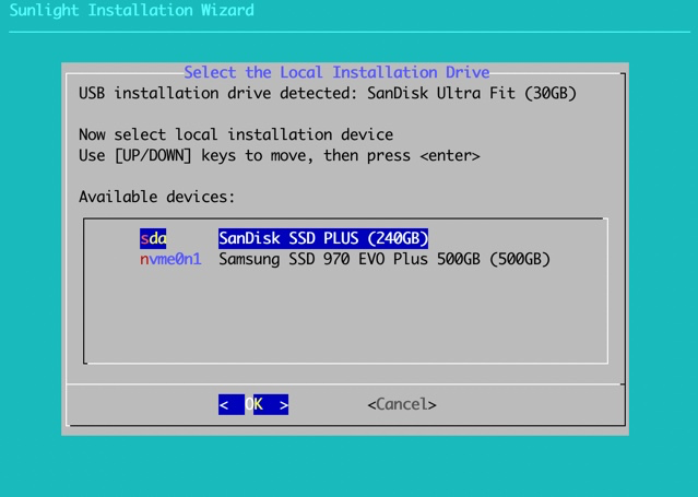
Select the local installation drive. This wizard is used to install the platform to the destination drive (local drive SATA/NVMe):
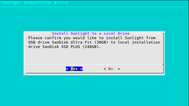
Please confirm your selection.
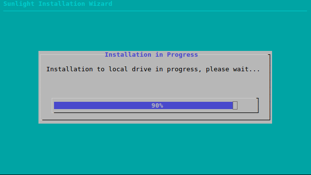
Check the installation progress bar.
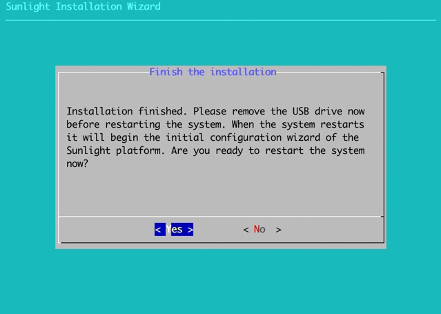
Once complete, the system will prompt you to remove the USB drive and reboot the system:
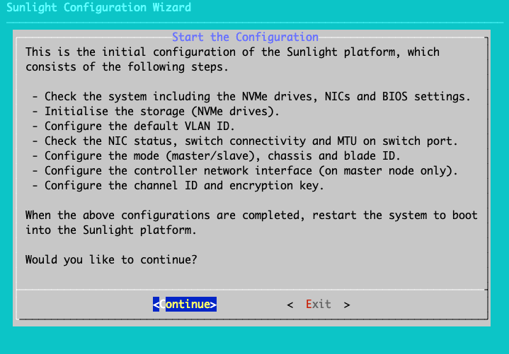
Following the reboot, the installation continues with the system's configurations.
System Configurations
Step 1 of 12
Press 'Continue' to check the hardware information
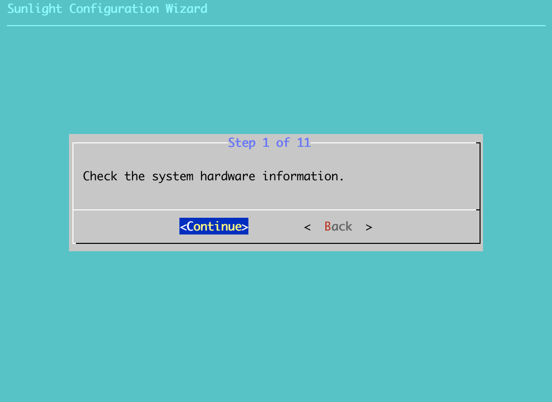
The initial step checks the system hardware information once again, in order to detect any hardware changes. Press ok to proceed (If the system still meets the requirements):
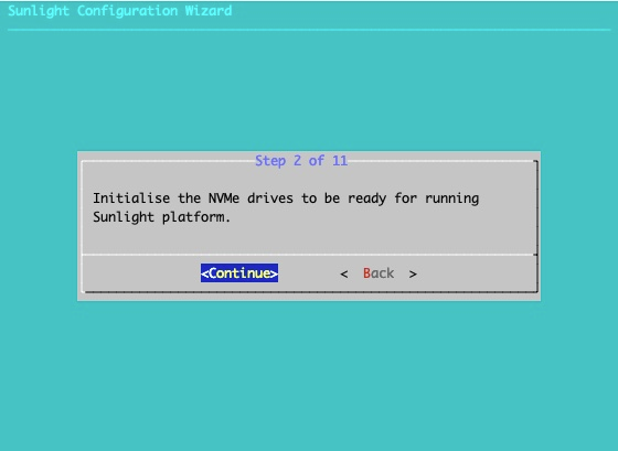
Step 2 of 12
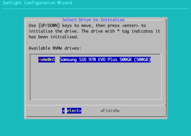
The second step is the initialisation of the NVMe drives. All NVMe drives must be initialised, in order to use them either for local/distributed storage (when the system is booted up and running) or for installation drive. Please select each drive on the list and go through the initialisation wizard.
Click continue:
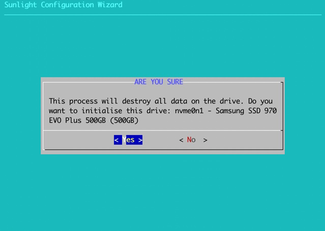
Choose the drive to initialise:
Select confirm, once the initialization process is completed:
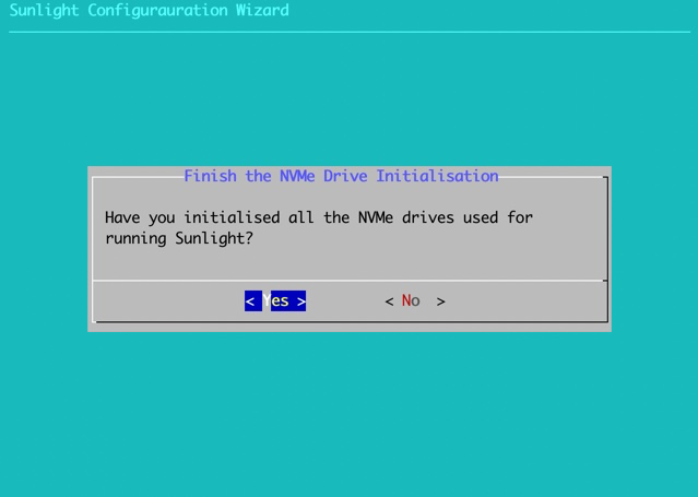
Once the initialisation of each desired NVMe drive is finalized, select 'Finish' to proceed.
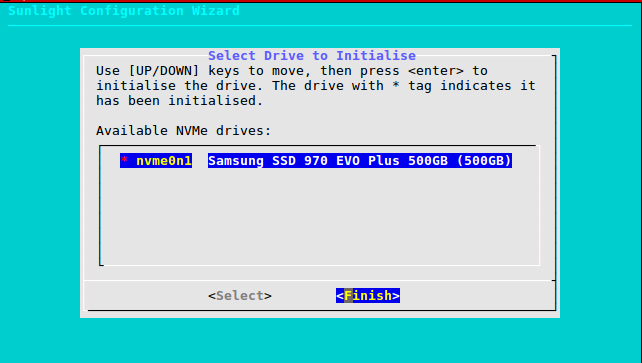
Please ensure that you have initialized all of your selected drives.
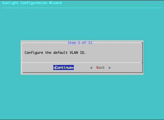
Step 3 of 12
Configure Virtual LANs. This option allows the configuration of the VLAN on the virtualised controller service, that runs when the system boots up. By enabling this VLAN feature, the system supports management network path redundancy in case of a network link failure. That means you have to enable this feature in order to support network redundancy for the management network of the system not for the virtual networks (VLAN) which the user can create after the installation.
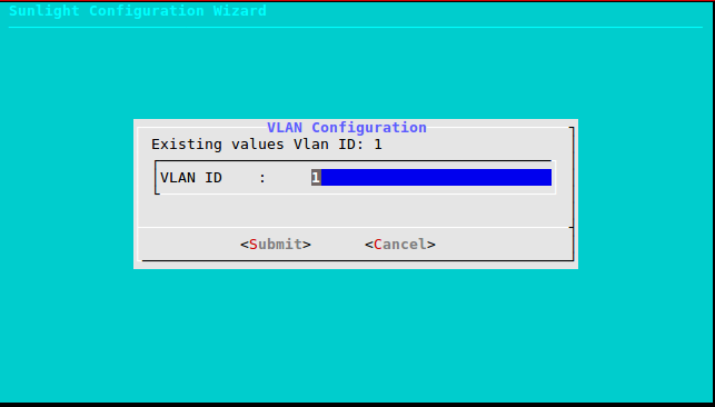
Two options are available, default and custom. The default option (defvlan = 1) disables the VLAN feature, while the custom option enables the VLAN feature with the selected value.
Note
The management network VLAN fault tolerance is independent of virtual network VLAN fault tolerance. The user can create a fault tolerant virtual network VLAN even if the management network VLAN has not been enabled during the installation.
Please select "Continue" to configure VLAN:
Select a custom value which will represent the VLAN ID, in order to activate this feature. Specify the default VLAN ID to 1, in order to deactivate the VLAN feature:
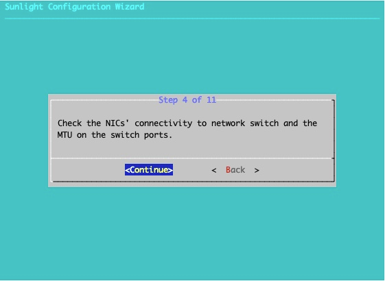
Step 4 of 12
The 4th step checks for network connectivity. If both 10GBit NICs have network connectivity and the MTU is properly configured (above 9000), the configuration process can continue:
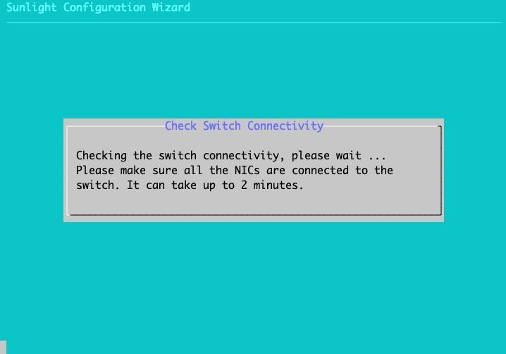
The following message is displayed in case there is a problem with the switch connectivity or the MTU of the ports is not properly configured:
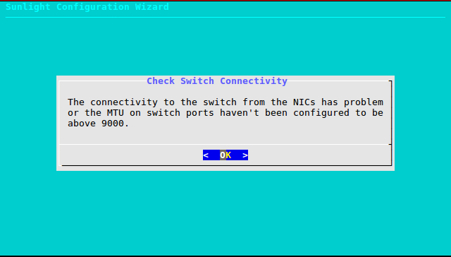
The user is notified of the problem, as depicted in the message below, in order to check and fix the switch configuration, before running the Sunlight platform at the end of the process.
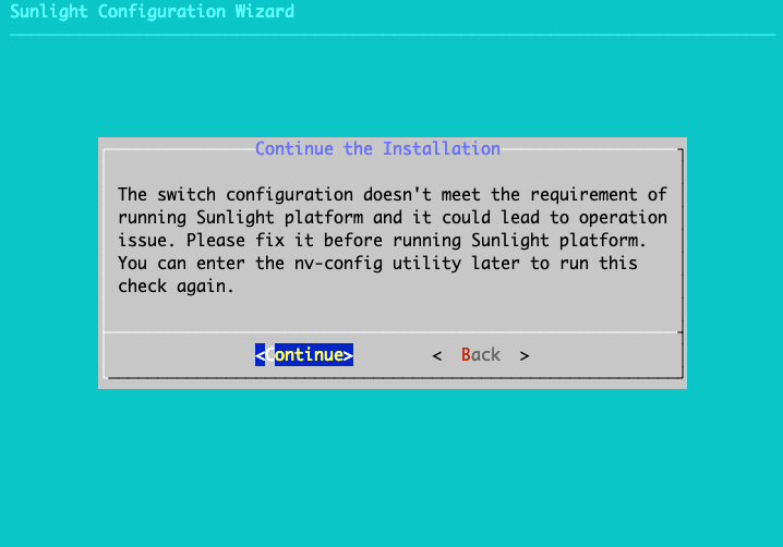
Please select "Continue" to proceed to the next step (Step 5). In case the switch is properly configured the installation proceeds seamlessly to Step 5.
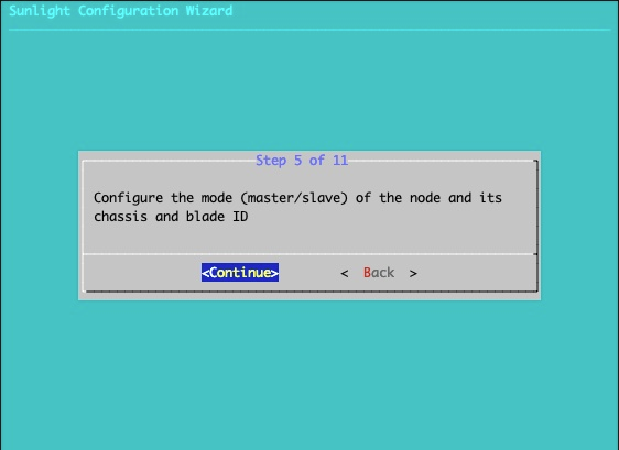
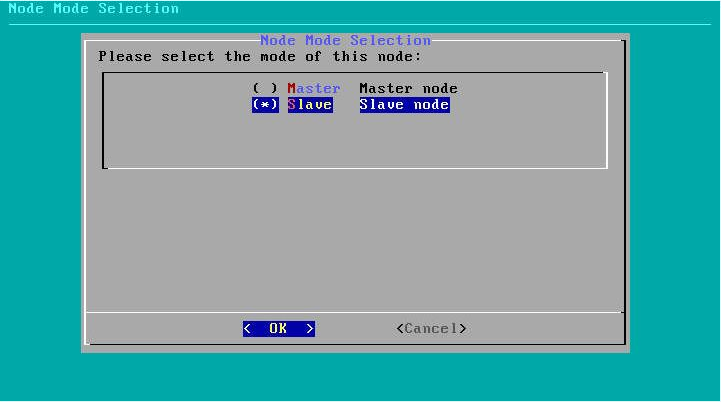
Step 5 of 12
Configure node mode. This option allows you to define the (master/slave) role of the installer node. Configure chassis and blade id. This option permits the definition of the chassis id as well as the blade id for the specific node being installed. The chassis ID should be a hexadecimal number,(e.g 0x2f1a), while the blade ID should be a decimal number (e.g. 1).
Please select "Continue" to proceed:
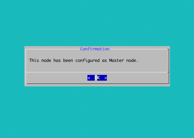
Choose master node mode (master node installation):
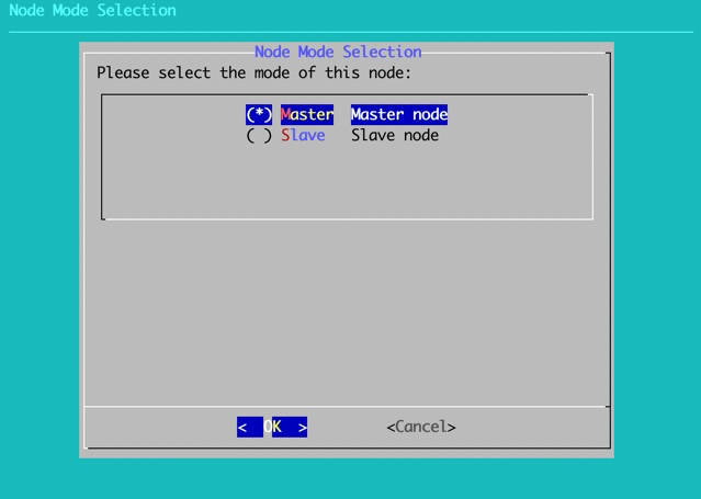
Accept and proceed:
OR
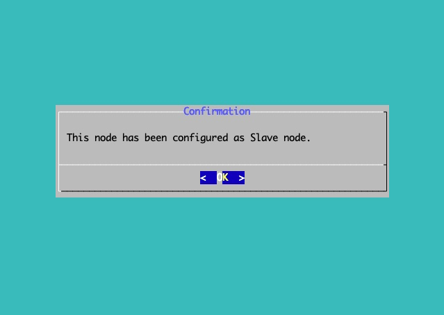
Choose slave node mode (slave node installation):
Accept and proceed:
Change the default values and press TAB to submit:
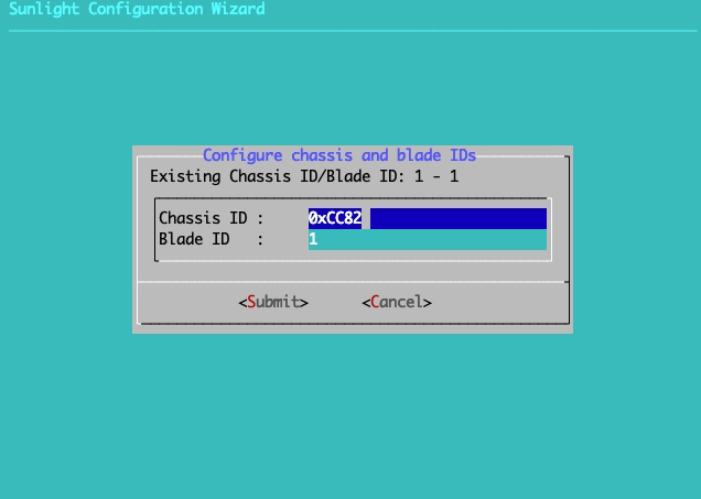
Warning
The Chassis id must be a Hex value in the format of "0x##" (e.g. 0xCC82). The Blade id must be a number between 1 and 99.
Step 6 of 12 (on master node only)
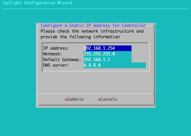
Configure controller network interface. This option allows the configuration of the IP address on the virtualised controller service that runs when the system boots up.
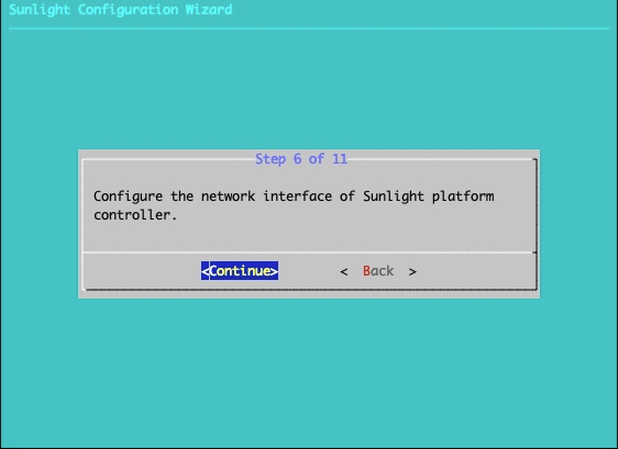
Two options are available, DHCP and static. For the static option, the IP address, net mask, default gateway and DNS settings of the controller can be specified.
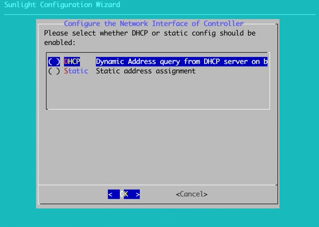
Provide dynamic DHCP settings:
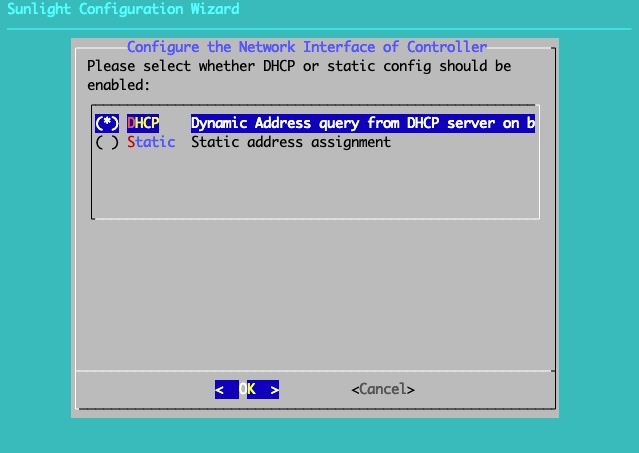
OR
Provide static settings:
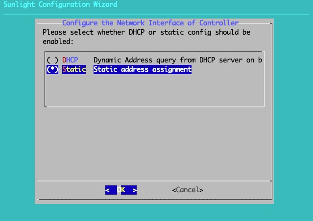
Specify the IP address of the host, the default Gateway, the Netmask and the DNS server:
Step 7 of 12
Enter size for the Amphora VDisk:
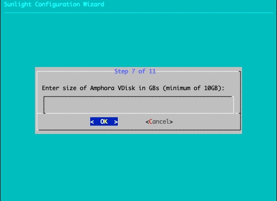
The size of the Amphora VDisk must be at least 10 GBs and cannot exceed the maximum available size of the installation disk (minus the size of the main and temporary Controller VDisks). We do provide some sanity checks to ensure a valid size is selected.
The Amphora disk is where downloaded templates and imported VM disks will reside. If you plan to use large templates like Windows or imported VMs we recommend a minimum of 100gb
Bare in mind that every template we download from a remote repository, is stored locally on the Amphora VDisk of the host of the controller. Thus, it is important to pick a size for the Amphora that will be enough to store the templates we intent to use.
If you don't pick any size, the VirtupianAPI will create an Amphora Vdisk with the maximum available size from the installation disk.
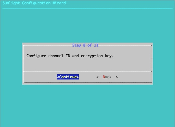
Step 8 of 12
Configure the NV channel and the encryption key. This option allows the configuration of the NV channel, which isolates clusters on the same subnet, according to the channel. The configuration of the encryption key is also provided, for allowing traffic to flow between the NVs with the same encryption key. As a result, the nodes that belong in the same cluster should be configured with the same channel id and encryption key, in order to detect each other.
Select "Continue" to proceed to the configuration:
Enter custom values and press TAB to submit:
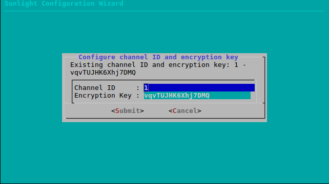
Warning
The Channel value must be a number between 1 and 65534.The Encryption key must be a string of exactly 16 characters (e.g. 0123456789abcdef).
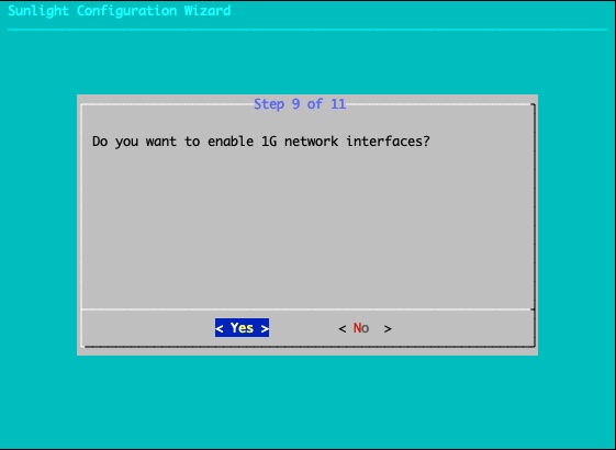
Step 9 of 12
Enable 1G network interfaces. This option allows you to enable the 1G network interfaces for the specific node. If you don't enable the 1G network interfaces, they will not be available for use and the management network will pass through the available 10G network interfaces.
Select "Yes" to enable the 1G network interfaces:
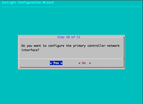
Step 10 of 12
Configure the controller primary network interface. The NexVisor uses the primary network, to create the Virtual network interface(VIF) for the Controller VM. The user will be able to access the Virtupian UI ,from that network interface. There is a provided list with all the available connected network interfaces. The 1G networks can be chosen, but its required from the user to enable the 1G network interfaces at the previous step. If you deny to choose a specific network interface, the NV will choose one of the available randomly.
Select "Yes" to configure the primary controller network interface.
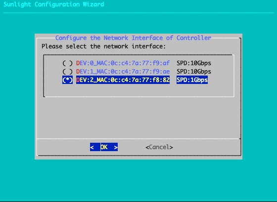
Select the primary network interface.
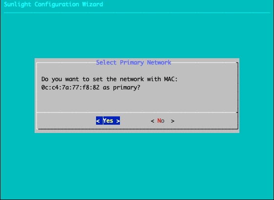
Confirm your choice.
Step 11 of 12
We have added as of version 4.2.0 a new installation option, whereas the user can define the mode of installation for the cluster.
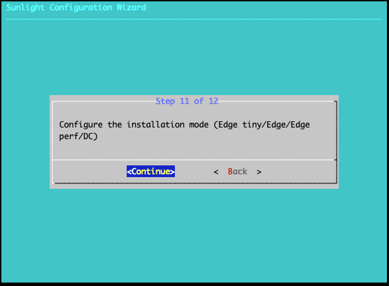
As mode of installation we define the preallocated resources needed by the cluster management layer in order to be functional.
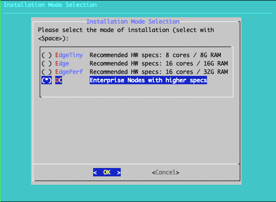
The suggested modes are:
- Edge tiny - 512MB RAM CONTROLLER - 512MB STORAGE, 1 shared core
- systems like RPi (less than 6 cores, less that 6GB RAM)
- Jetson with up to 8 cores and 8GB of RAM
- Other small IOT devices of the future etc
- Edge - 1GB RAM CONTROLLER - 512MB RAM STORAGE, 1 shared core
- systems with up to 16 cores and 16 GB RAM
- Edge performance - 2GB RAM CONTROLLER - 1GB RAM STORAGE, 2 shared cores
- systems with up to 16 cores and 32 GB RAM
- DC - 4GB RAM CONTROLLER - 2GB RAM STORAGE, 2 shared cores
- dc enterprise systems (bobcats etc)
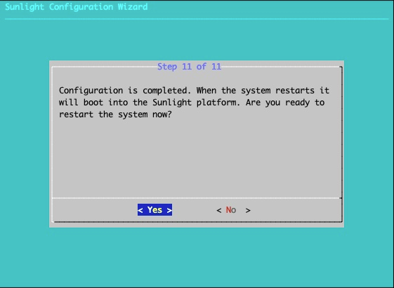
Step 12 of 12
Exit and restart. This step will reboot the system back to the initial boot menu.
Confirm reboot option:
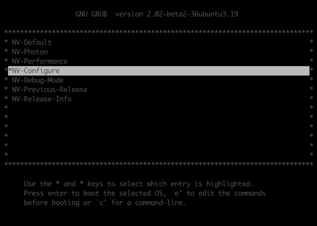
After rebooting, you can view the following menu options that are provided. You can choose NV-Configure, in order to change the configuration settings:
Following the configuration options described above, the controller UI will boot up with the declared IP settings, or a default pre-configured IP address:
| IP Address | 192.168.1.254 (link) |
| Netmask | 255.255.255.0 |
| Default Gateway | 192.168.1.1 |
| Default Username | administrator |
| Default Password | NexVisor |
Now the system is booted up and fully operational. Please configure a local method to access the ethernet segment with the network settings outlined above. The duration for the cluster controller to boot up is approximately one minute, however a web browser can be pointed at the IP address of the controller UI, which has been previously configured in Step 6. The following screen is displayed upon the boot up: